
OpenFOAM® v3.0+: New Numerics Functionality
13/01/2016
Mesh motion: new point interpolation methods
Finite volume based mesh motion solvers calculate a cell-centred displacement field. This is interpolated to the internal points using volume-to-point interpolation. Boundary points on value patch types are not given the interpolated value, however; their displacements are set by the relevant boundary condition. The inconsistency between the boundary points and the points in the interior can result in an accumulation of error as the point displacement increases. For very thin layer cells, this error can result in the boundary-adjacent cell becoming significantly distorted.
In this release all finite volume based mesh motion solvers now support user-selectable volume-to-point interpolation methods through an optional interpolation entry. A new method, patchCorrected, improves the behaviour for the thin layer scenario above. It combines interpolation of the cell-centred displacement with an interpolation of the prescribed boundary motion across the whole domain using a point-based interpolation method. The method requires the specification of at least two sets of patch groups. Ideally, these patch groups will be facing one another. For example:
solver displacementLaplacian;
displacementLaplacianCoeffs
{
diffusivity quadratic inverseDistance (aerofoilUpper aerofoilLower);
interpolation patchCorrected ((aerofoilUpper aerofoilLower) (farField));
}
displacementLaplacianCoeffs
{
diffusivity quadratic inverseDistance (aerofoilUpper aerofoilLower);
interpolation patchCorrected ((aerofoilUpper aerofoilLower) (farField));
}
Only patches which specify a value for the motion should be specified. This includes fixedValue conditions and all derived types. Patches with slip, empty and zeroGradient conditions should not be included in any group.
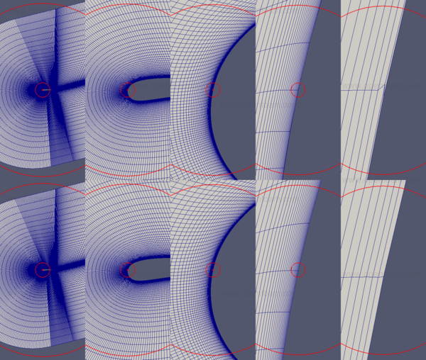
The picture below shows an example of the improved layer motion for an airfoil case, where the top image shows the original method with strong distortion near to the wall, compared with the improved form.
- Source code
- $FOAM_SRC/src/fvMotionSolver/motionInterpolation
Convection Scheme for Detached Eddy Simulation
A new hybrid convection scheme for use with Detached Eddy Simulation (DES) is now available, which blends between a low-dissipative convection scheme within the LES region, e.g. linear, and a numerically more robust convection scheme in the RAS region, e.g. upwind-biased schemes.
Based on the references:
- 1
- A. Travin, M. Shur, M. Strelets, P. Spalart (2000). Physical and numerical upgrades in the detached-eddy simulation of complex turbulent flows. In Proceedings of the 412th Euromech Colloquium on LES and Complex Transition and Turbulent Flows, Munich, Germany
- 2
- P. Spalart, M. Shur, M. Strelets, A. Travin (2012). Sensitivity of Landing-Gear Noise Predictions by Large-Eddy Simulation to Numerics and Resolution. AIAA Paper 2012-1174, 50th AIAA Aerospace Sciences Meeting, Nashville / TN, Jan. 2012
Example of the DEShybrid scheme specification using linear within the LES region and linearUpwind within the RAS region:
divSchemes
{
div(phi,U) Gauss DEShybrid
linear // scheme 1
linearUpwind grad(U) // scheme 2
0.65 // DES coefficient, typically = 0.65
30 // Reference velocity scale
2 // Reference length scale
0 // Minimum sigma limit (0-1)
1; // Maximum sigma limit (0-1)
}
{
div(phi,U) Gauss DEShybrid
linear // scheme 1
linearUpwind grad(U) // scheme 2
0.65 // DES coefficient, typically = 0.65
30 // Reference velocity scale
2 // Reference length scale
0 // Minimum sigma limit (0-1)
1; // Maximum sigma limit (0-1)
}
This feature was initially supplied by CFD Software E+F GmbH and integrated by OpenCFD.
- Source code
- DESHybrid - $FOAM_SRC/TurbulenceModels/schemes/DEShybrid
Velocity damping
A constraint to dampen velocity fluctuations in steady simulations has been added. In case of velocity exceeding a limit, it applies a source/sink to remove the excess velocity by adding a term that drives the velocity to 0 (note that we cannot use the old time velocity since it most likely is already excessive). This additional constraint is scaled with
 |
where  is a local time scale given by velocity/cellsize so it switches off if the
velocity is below UMax.
is a local time scale given by velocity/cellsize so it switches off if the
velocity is below UMax.
The number of cells limited will be displayed and should fall to 0 as the simulation proceeds.
Usage:
The constraint can be activated by adding following to the $FOAM_CASE/system/fvOptions dictionary:
damp
{
type velocityDampingConstraint;
active true;
velocityDampingConstraintCoeffs
{
UMax 100;
// Optional: name of velocity field (default: U)
// UName U;
}
}
{
type velocityDampingConstraint;
active true;
velocityDampingConstraintCoeffs
{
UMax 100;
// Optional: name of velocity field (default: U)
// UName U;
}
}
- Source code
- Velocity Damping - $FOAM_SRC/fvOptions/constraints/derived/velocityDampingConstraint