OpenFOAM® v3.0+: New Boundary Conditions Functionality
13/01/2016
Periodic Arbitrary Mesh Interface
A new type of cyclic matching patch, cyclicPeriodicAMI enables conformal mapping of periodic geometries, e.g. wedge geometries.
It uses the transformation provided by the periodic patches to also transform the matching surface which is then handled by the standard cyclicAMI functionality.
A cyclicPeriodicAMI patch relaxes the matching requirement of standard AMI patches. The code will firstly calculate the AMI overlap as normal. If there are non-overlapping regions remaining, the patches will be moved according to the transformation of another pair of (probably cyclic) coupled patches. This will continue until the overlap is complete, or a pre-set number of iterations is reached. If the overlap is not complete, an error is generated, and the program exits.
The algorithm allows for one patch to be an integer multiple of the other. A 20 deg sector could be coupled to a 60deg sector, for example, but not to a 50 deg sector. If the multiple is not an integer, the program will exit with an error.
- Example
- Combustor: $FOAM_TUTORIALS/combustion/XiDyMFoam/annularCombustorTurbine
![[Picture]](/releases/openfoam-v3.0+/img/boundaryConditions-periodicAMI-small.png)
- Source code
- $FOAM_SRC/meshTools/AMIInterpolation/patches/cyclicPeriodicAMI/cyclicPeriodicAMIPolyPatch/
- Related files
- $FOAM_SRC/meshTools/AMIInterpolation/AMIInterpolation/AMIInterpolation.[CH]
$FOAM_SRC/meshTools/AMIInterpolation/patches/cyclicAMI/cyclicAMIPointPatch/cyclicAMIPointPatch.C
$FOAM_SRC/finiteVolume/fvMesh/fvPatches/constraint/cyclicAMI/cyclicAMIFvPatch.C
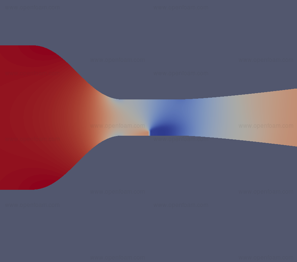
Windtunnel nozzle boundary condition
The new pressurePIDControlInletVelocity tries to generate an inlet velocity that maintains a specified pressure drop between two face zones downstream.
Wind tunnels are calibrated by correlating a pressure drop in the nozzle with the dynamic head, and therefore velocity, in the working section. It is typically desired to run a simulation at a specified working section velocity. This is difficult to specify manually by means of standard boundary conditions.
The face zones should fully span a duct through which all the inlet flow passes. An incompressible, lossless analysis of the flow between the inlet and the two face-zones is performed. An ideal inlet velocity is thereby calculated from the user-specified pressure drop. The analysis includes a transient term when running a transient simulation.
Users can select the boundary condition as follows:
inlet
{
type pressurePIDControlInletVelocity;
deltaP 200;
shapeFactor 0;
upstream upstreamFaceZoneName;
downstream downstreamFaceZoneName;
P 0.01;
I 0.005;
D 0.002;
value uniform (0 0 0);
}
{
type pressurePIDControlInletVelocity;
deltaP 200;
shapeFactor 0;
upstream upstreamFaceZoneName;
downstream downstreamFaceZoneName;
P 0.01;
I 0.005;
D 0.002;
value uniform (0 0 0);
}
The two face zones are specified by their names as upstream and downstream, and the desired pressure drop between them is given as deltaP. A positive pressure drop indicates that the upstream pressure is higher than the downstream value.
The shapeFactor describes the amount of non-linearity in the nozzle geometry.
The control algorithm uses the coefficients  ,
,  and
and  . These are
standard proportional, integral and derivative gains.
. These are
standard proportional, integral and derivative gains.
A p entry may be specified to use a non-standard name for the pressure field, e.g.p_rgh. For compressible cases, a rho entry can also be used to specify the name of the density field (Note that the rho field is only used for calculation of the volumetric flow rate; the pressure drop analysis still assumes incompressible flow).
- Source code
- $FOAM_SRC/src/finiteVolume/fields/fvPatchFields/derived/pressurePIDControlInletVelocity
Humidity
A new boundary condition for temperature has been implemented to thermally couple flow and solid regions when condensation/evaporation is expected on the interface.
The boundary condition is named humidityTemperatureCoupledMixed, and can operate in four modes:
- inert : thermal inertia is important and no condensation/evaporation takes place;
- condensation : condensation only;
- vaporization : evaporation only;
- condensationAndEvaporation : both condensation and evaporation take place.
The boundary condition assumes no mass flow on the wall i.e. the mass condensed on a patch face remains on that face, and uses a lumped mass model to include thermal inertia effects. The correlation used to calculate the dew temperature based on water vapour.
A scalar transport equation for the carrier specie must be specified via a function object or in the main solver. This transports the vapour phase in the main region. The boundary condition applied to this specie on the coupled wall should be fixedGradient in order to allow condensation or evaporation of the vapour in or out of wall.
- Example
- Windshield: $FOAM_TUTORIALS/heatTransfer/chtMultiRegionFoam/windshieldCondensation
![[Picture]](/releases/openfoam-v3.0+/img/physics-humidity-small.png)
- Source code
- $FOAM_SRC/TurbulenceModels/compressible/turbulentFluidThermoModels/derivedFvPatchFields/humidityTemperatureCoupledMixed