
OpenFOAM® v3.0+: New Solver and Physical Modelling Functionality
13/01/2016
DES Models: New and Updated
The existing family of Spalart-Allmaras DES models has been updated, and a new family of models based on the kOmegaSST model implemented, based on the references:
- kOmegaSSTDES
- Strelets, M. (2001), Detached Eddy Simulation of Massively Separated Flows, 39th AIAA Aerospace Sciences Meeting and Exhibit, Reno, NV
- kOmegaSSTDDES
- Gritskevich, M.S., Garbaruk, A.V., Schuetze, J., Menter, F.R. (2011), Development of DDES and IDDES Formulations for the k-omega Shear Stress Transport Model, Flow, Turbulence and Combustion
- kOmegaSSTIDDES
- Gritskevich, M.S., Garbaruk, A.V., Schuetze, J., Menter, F.R. (2011), Development of DDES and IDDES Formulations for the k-omega Shea r Stress Transport Model, Flow, Turbulence and Combustion
The picture below shows the validation and calibration of OpenFOAM DES models for decaying isotropic turbulence.
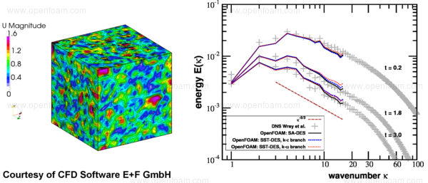
This feature was initially supplied by CFD Software E+F GmbH and integrated by OpenCFD.
- Source code
- DES Model - $FOAM_SRC/TurbulenceModels/turbulenceModels/DES/kOmegaSSTDES
DDES Model - $FOAM_SRC/TurbulenceModels/turbulenceModels/DES/kOmegaSSTDDES
IDDES Model - $FOAM_SRC/TurbulenceModels/turbulenceModels/DES/kOmegaSSTIDDES
Solar Load
A new radiation model has been implemented to model the effects of solar radiation. The new solarLoad model includes the sun primary heat fluxes, their reflective fluxes on walls, and the diffusive sky radiative fluxes.
- The primary hit rays are calculated using a face shading algorithm;
- The reflected fluxes are considered diffusive and use a view factors method to distribute the energy on ‘visible’ walls.
The sky diffusive radiation for horizontal and vertical walls is calculated according to The Fair Weather Conditions Method from the ASHRAE Handbook.
By default, energy in cells adjacent to the patches are included in the energy equation (wallCoupled set to false in the radiation dictionary). On coupled patches (for multi-region cases) the flux is added to the wall heat flux by default and is considered into the solid (solidCoupled set to true). The reflected fluxes use a grey absorption/emission model, weighted by the spectral distribution. In order to activate the reflected fluxes the useVFbeamToDiffuse flag should be set to true, and the view factors calculated using the viewFactorsGen application.
The solarLoad model can be used inconjunction with fvDOM, viewFactor and P1 radiation models - but only using a single band spectrum. On the corresponding boundary conditions for these models the flag solarLoad must be set to true to take the solar radiative heat flux into account.
The new solar calculator model generates information related to the sun direction. The available models are:
- sunDirConstant: the direction is given in ‘sunDirection’
- sunDirTracking: the direction is calculated from the following parameters:
This model should be use in transient calculations. The keyword sunTrackingUpdateInterval (in hours) specifies on which interval the sun direction is updated.(Local Zone Meridian) in hours
localStandardMeridian : GMT
startDay : day from 1 to 365
startTime : in hours
longitude : in degrees
latitude : in degrees
gridUp : grid orientation upwards
gridEast : grid orientation eastwards
The following new solar load models are available:
- sunLoadConstant: Direct and diffusive heat fluxes are specified by the user;
- sunLoadFairWeatherConditions: The solar fluxes are calculated following the Fair Weather Conditions Method from the ASHRAE Handbook.
- sunLoadTheoreticalMaximum: The solar fluxes are proportional to the top of the atmosphere direct normal solar irradiance and a correction to account for reduction in solar load through the atmosphere.
The diffuse on vertical/horizontal walls and ground-reflected radiation are calculated following the ASHRAE Handbook.
- Usage change
- From this version the radiative properties, e.g. emissivity, absorptivity and transitivity of the patch, are given in the file $FOAM_CASE/constant/boundaryRadiationProperties on a per-patch basis.
- Note
- The number of bands in the Solar Load model MUST be the same as the number of bands specified on patches of the boundaryRadiationProperties file.
There are three modes that a model can be specified:
- lookup: The values are entered on the patch_name as: patch_name
{
type boundaryRadiation;
mode lookup;
emissivity uniform 1.0;
absorptivity uniform 0.0;
transmissivity uniform 1.0;
} - solidRadiation: This model is used for multi-region cases where the
properties are looked at on the solid thermo. This is used when is a
coupled BC with a solid. The emissivity, etc. are specified in the
constant/thermophysicalProperties in the solid region. air_to_solid
{
type boundaryRadiation;
mode solidRadiation;
value uniform 0;
} - model: A model for each property can be used. This is used for multi band
models: minZ
{
type boundaryRadiation;
mode model;
absorptionEmissionModel multiBandSolidAbsorptionEmission;
multiBandSolidAbsorptionEmissionCoeffs
{
absorptivity (0.8 0.8);
emissivity (0.8 0.8);
}
transmissivityModel multiBandSolidTransmissivity;
multiBandSolidTransmissivityCoeffs
{
transmissivity (0 0);
}
value uniform 0.0;
}
- Examples
- externalSolarLoad: $FOAM_TUTORIALS/heatTransfer/chtMultiRegionFoam/externalSolarLoad
![[Picture]](/releases/openfoam-v3.0+/img/physics-solar-load-flux_combined_result-small.png)
- Source code
- $FOAM_SRC/thermophysicalModels/radiation/radiationModels/solarLoad
$FOAM_SRC/thermophysicalModels/radiation/submodels/solarCalculator
New Diffusion-based Turbulent Combustion Model
A new turbulent diffusion combustion model named diffusionMulticomponent for multiple step reactions has been implemented. The model assumes single a stream of fuel and oxidant for each reaction.
The reaction rate is based on the magnitude of the product of fuel and oxidant turbulence fluxes.
A finite reaction rate can be used to initialise the reaction rate, typically for lower temperature regions away from the mixing zone or during ignition using the laminarIgn option.
A normalised Gaussian distribution, centred at the stoichiometry value of each reaction, positions the flame in mixture fraction space. Users may specify the standard deviation of the Gaussian distribution. The probability distribution is moderated by a dynamic constant based on the amount of oxidant remaining in each reaction.
The diffusion reaction rate for k equation is given by:
 |
where  is the effective diffusion,
  the normalized Gaussian
distribution centred on the stoichiometry value, and
the normalized Gaussian
distribution centred on the stoichiometry value, and  a dynamic model
constant, defined as:
a dynamic model
constant, defined as:
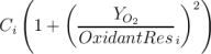 |
where  is the oxidant remaining in each reaction (user input) and
  a model constant with a default value of 1.
- Examples
- smallPoolFire2D: $FOAM_TUTORIALS/combustion/fireFoam/les/smallPoolFire2D
See note in file $FOAM_CASE/constant/combustionProperties in order to activate the model
![[Picture]](/releases/openfoam-v3.0+/img/physics-diffusion-combustion-all-small.png)
The pictures show the results after 3 seconds of fuel injection from the bottom injector into the atmosphere for the flame front, shown by the heat release contour, and temperature contours.
- Source code
- diffusionMulticomponent $FOAM_SRC/combustionModels/diffusionMulticomponent
Moving Mesh Combustion Solver
The new XiDyMFoam solver provides a moving mesh version of the partially premixed combustion solver XiFoam. The differences between the two solvers are small, and are similar to the extensions visible in rhoPimpleDyMFoam over rhoPimpleFoam.
Cases set up for this solver should be very similar to those designed for XiFoam. An additional divergence scheme is required for the selection of the mesh flux and pressure. This is specified in system/fvSchemes.
divSchemes
{
div(meshPhi,p) Gauss linear;
// etc ...
}
{
div(meshPhi,p) Gauss linear;
// etc ...
}
The solver also requires an entry for the pressure correction pcorr resulting from the mesh motion in the system/fvSolution file. This can usually be specified as identical to the pressure solver, but with a higher tolerance.
solvers
{
pcorr
{
$p;
tolerance 1e-02;
relTol 0;
}
// etc ...
}
{
pcorr
{
$p;
tolerance 1e-02;
relTol 0;
}
// etc ...
}
Finally a constant/dynamicMeshDict file is required to specify the mesh motion.
- Examples
- annularCombustorTurbine: $FOAM_TUTORIALS/combustion/XiDyMFoam/annularCombustorTurbine
oscillatingCylinder: $FOAM_TUTORIALS/combustion/XiDyMFoam/oscillatingCylinder
- Source code
- Moving Mesh Combustion Solver - $FOAM_SOLVERS/combustion/XiFoam/XiDyMFoam/*
Steady-State Lagrangian Coal Combustion Solver
A new steady lagrangian solver which uses ‘coal’ parcels has been implemented: simpleCoalParcelFoam. The solver is very similar to the existing transient coalChemistryFoam solver.
The solver employs a single cloud of coal particles, which can undergo evaporation of any liquid/vapour content and devolatilisation to the carrier phase, and surface reactions. The carrier phase includes support for turbulence, heat transfer and combustion modelling.
The solver is based on the rhoThermoCombustion combustion class and therefore the thermo type must be set to heRhoThermo.
- Source code
- simpleCoalParcelFoam - $FOAM_APP/solvers/lagrangian/simpleCoalParcelFoam
Inter-Region Heat Transfer
The new tabulatedNTUHeatTransfer inter-region heat transfer model calculates the heat flux between separate regions based on the Number of Transfer Units (NTU).
Usage: The model inputs are similar to the tabulatedHeatTransfer on which this model is based, e.g.
exchangerToAir
{
type tabulatedNTUHeatTransfer;
active yes;
tabulatedNTUHeatTransferCoeffs
{
interpolationMethod cellVolumeWeight;
nbrRegionName air;
master true;
fieldNames (h);
outOfBounds clamp;
fileName "ntuTable";
nbrModelName airToExchanger;
semiImplicit no;
geometryMode user; // user | calculated
...
}
}
{
type tabulatedNTUHeatTransfer;
active yes;
tabulatedNTUHeatTransferCoeffs
{
interpolationMethod cellVolumeWeight;
nbrRegionName air;
master true;
fieldNames (h);
outOfBounds clamp;
fileName "ntuTable";
nbrModelName airToExchanger;
semiImplicit no;
geometryMode user; // user | calculated
...
}
}
Additional parameters are required to define the geometryMode of the heat exchanger. Two options are available:
- user: user specifies inlet areas and (optional) core volume geometryMode user;
// Exchanger inlet area
Ain 0.02;
// Air-side inlet area
AinNbr 0.35;
// Optional core volume - automatically calculated if not present
Vcore 0.01; - calculated: information retrieved from the model directly geometryMode calculated;
// Name of exchange inlet patch
inletPatch inlet_exchanger;
// Name of air-side inlet patch
inletPatchNbr inlet_air;
// Proportion of inlet patch blocked (inactive), using 10% here
inletBlockageRatio 0.10;
// Proportion of inlet patch blocked (inactive), using 4% here
inletBlockageRatioNbr 0.04;
// Proportion of core volume blocked (inactive), using 0% here
coreBlockageRatio 0;
This feature was initially supplied by CFD+Engineering GmbH and integrated by OpenCFD.
- Source code
- NTU heat transfer - $FOAM_SRC/fvOptions/sources/interRegion/interRegionHeatTransfer/tabulatedNTUHeatTransfer