v2212: New and improved numerics
TOP
The overset framework has been extended to:
- allow overset patches to extend outside the background domain;
- allow fringe faces away from the hole cells in the background domain; and
- add an option to improve mass conservation.
Overset patches outside the domain
Cells that reside outside of all other meshes cannot use interpolation due to missing donor cell candidates. These cells can be treated using the new porous cell type, which solves for the cell locally, similar to regular calculated cells. As these cells are normally close to wall patches they usually require some damping to maintain stability of the pressure-velocity system. This can be applied using, e.g. an fvOption to damp the velocity, where the new cellType selectionMode entry can identify the porous cells:
limitU
{
    type            velocityDampingConstraint;
    active          true;
    selectionMode   cellType;
    UMax            0;
    C               1;
}
Tests employing inverseDistance, trackingInverseDistance, and volumeWeight cell stencils indicated a damping constant, C, of '1' tended to work well.
Please note that this approach does not support the overlapping of two inset meshes on top of the background mesh.
Allow fringe faces away from the hole cells in the background domain
The overset approach benefits when the interpolated cells are away from areas where the flow exhibits high gradients. In earlier versions, geometrically obscured cells (type hole) were surrounded by interpolated cells. In this release, interpolated cells can be moved further away from obstructions using the oversetInterpolation section in the system/fvSchemes dictionary:
oversetInterpolation
{
    method              inverseDistance;
    ..
    holeLayers          4;
    useLayer            2;
}
The holeLayers entry specifies the number of cell layers to 'walk' away from hole cells, and useLayer the layer number to place the interpolation cells, i.e. in the example above, a walk comprising 4 layers will be performed, where layer 2 will be used to place the interpolation.
On execution, the solver reports the average ratio of the layer volume on each mesh, e.g.:
Number of layers : 4
Average volumetric ratio : 4(0.9581398507 0.9624422346 0.966612743 0.97065     73485)
Number of holes cells : 4(202 203 204 205)
Using layer : 2
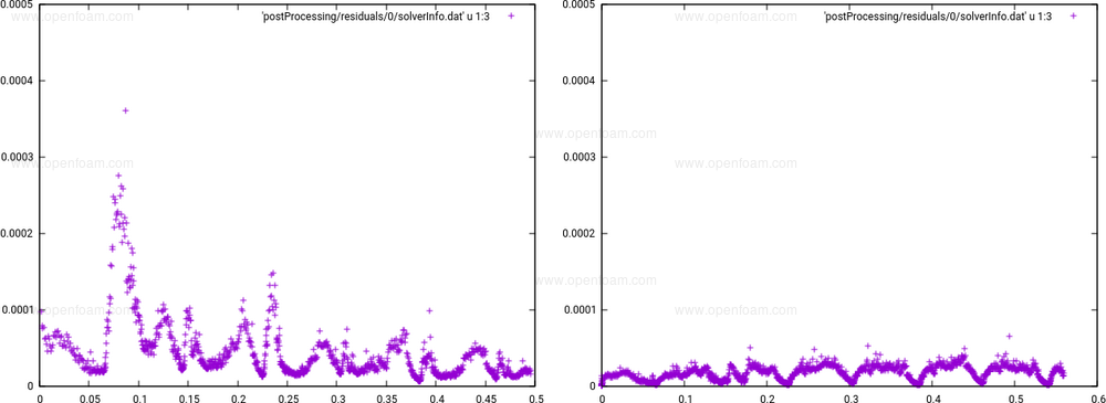
The following is typical of the improvement expected on pressure residuals:
Options to improve overset mass conservation
Earlier experimental keywords have been removed from the overset-based solver applications, i.e. massFluxInterpolation, ddtCorr, and correctPhi. Mass conservation has been improved with the addition of a flux correction, controlled by the new oversetAdjustPhi keyword in the fvSolution file:
PIMPLE
{
    momentumPredictor   no;
    nOuterCorrectors    1;
    nCorrectors         3;
    nNonOrthogonalCorrectors 0;

    oversetAdjustPhi    true;
}
This flag adjusts the flux across fringe faces in the inner PIMPLE loop. The following images show the effect on mass conservation for the $FOAM_TUTORIALS/multiphase/overInterDyMFoam/simpleRotor case, where the first is computed without the correction, and the second with the correction.
A second option for flux/mass conservation is the implicit correction, specified on the patch field:
free
{
    type            overset;
    value           uniform 300;
    fluxCorrection  true;
}
This implements a flux correction using a flux constraint inside the linear solver. It enforces the conservation constraint on all fringe faces for every matrix-field multiplication. Note that this is applied to the preconditioned variable in a preconditioned conjugate gradient system, and therefore may have limited benefit. In the overLaplacianDyMFoam tutorial basic/overLaplacianDyMFoam/1DheatTransferMassConservation, enabling the fluxCorrection improves the performance of overset patches.
Source code
Tutorials
Outside cells:
- $FOAM_TUTORIALS/multiphase/overInterDyMFoam/twoSquaresOutDomain
- $FOAM_TUTORIALS/incompressible/overPimpleDyMFoam/rotatingSquare
Fringe faces:
- $FOAM_TUTORIALS/incompressible/overPimpleDyMFoam/simpleRotor
- $FOAM_TUTORIALS/multiphase/overInterDyMFoam/floatingBody
- $FOAM_TUTORIALS/multiphase/overInterDyMFoam/rigidBodyHull
Mass conservation (explicit):
Mass conservation (implicit):
TOP
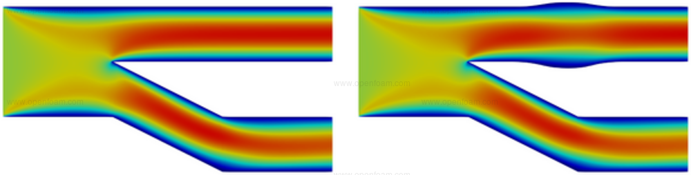
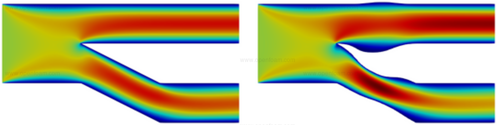


Five new objective functions for use in adjoint-based optimisation have been added, mainly targetting internal flow optimisation problems. A short description and an indicative example for each of them follows. All figures that follow depict the velocity magnitude.
flowRate
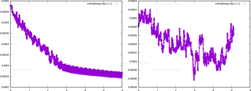
Computes and minimizes/maximizes the volume-flow rate through a given set of patches. An indicative application follows, in which the flow-rate through the upper part of the duct should be maximized (flow from left to right).
Tutorial: $FOAM_TUTORIALS/incompressible/adjointOptimisationFoam/shapeOptimisation/fork-uneven/flowRate
Source code: $FOAM_SRC/optimisation/adjointOptimisation/adjoint/objectives/incompressible/objectiveFlowRate
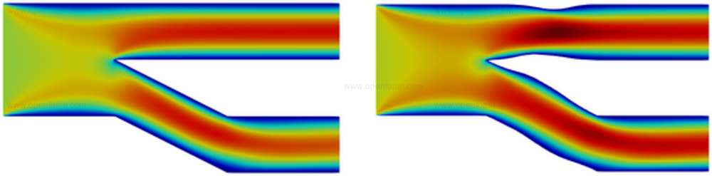
flowRatePartition
Used to distribute the inlet flow-rate to outlet patches with prescribed target percentages. An indicative application follows, in which the equal distribution of the inlet flow-rate to the two outlets is targeted.
Tutorial: $FOAM_TUTORIALS/incompressible/adjointOptimisationFoam/shapeOptimisation/fork-uneven/flowRatePartition
Source code: $FOAM_SRC/optimisation/adjointOptimisation/adjoint/objectives/incompressible/objectiveFlowRatePartition
uniformityPatch
Enhances the flow uniformity by minimizing the velocity variance computed on prescribed (outlet) patches (the lower outlet patch in this case).
Tutorial: $FOAM_TUTORIALS/incompressible/adjointOptimisationFoam/shapeOptimisation/fork-uneven/uniformityPatch
Source code: $FOAM_SRC/optimisation/adjointOptimisation/adjoint/objectives/incompressible/objectiveUniformityPatch
uniformityCellZone
Enhances the flow uniformity by minimizing the velocity variance within prescribed cellZones.
In this case, the boundaries of the target cellZone are highlighted in black.
Tutorial: $FOAM_TUTORIALS/incompressible/adjointOptimisationFoam/shapeOptimisation/sbend/laminar/opt/unconstrained/uniformityCellZone
Source code: $FOAM_SRC/optimisation/adjointOptimisation/adjoint/objectives/incompressible/objectiveUniformityCellZone
powerDissipation
Computes and minimizes the fluid power dissipation that takes place within given cellZones. If the cellZone covers the entire flow domain, this objective is equivalent to volume flow-rate weighted total pressure losses (i.e. the PtLosses objective function).
The boundaries of the target cellZone are highlighted in black.
Tutorial: $FOAM_TUTORIALS/incompressible/adjointOptimisationFoam/shapeOptimisation/sbend/turbulent/SA/opt/powerDissipation
Source code: $FOAM_SRC/optimisation/adjointOptimisation/adjoint/objectives/incompressible/objectivePowerDissipation
Attribution
- The software was developed by PCOpt/NTUA and FOSS GP
- Integration in collaboration with OpenCFD on MR!578
User guide
- A PDF guide prepared by NTUA is available here
TOP
The new parallel geometry calculation method can be applied as a wrapper around other geometry calculation methods:
geometry
{
    type            parallel;
    // Optional underlying geometry calculation. Default is 'basic'.
    geometry
    {
        type            highAspectRatio;
    }
}
It operates by applying the owner side face geometry to the neighbour side, i.e. the face centre, normal (negated), and recalculating the cell-based geometry of affected cells.
This is particularly beneficial for single-precision cases, where it removes the truncation error resulting from the different calculation orders employed by coupled patches that can cause problems when calculating global transformations, e.g.
 --> FOAM FATAL ERROR: (openfoam-2206)
 bad size -653174757

     From void Foam::List<T>::doResize(Foam::label) [with T = Foam::vectorTensorTransform; Foam::label = int]
     in file lnInclude/List.C at line 84.


 #0  Foam::error::printStack(Foam::Ostream&)
 #1  Foam::error::simpleExit(int, bool) at ??:?
 #2  Foam::error::exiting(int, bool)
 #3  Foam::List<Foam::vectorTensorTransform>::doResize(int)
 #4  Foam::globalIndexAndTransform::determineTransformPermutations() at ??:?
Note that the parallel scheme does not change the point positions, meaning any other calculated geometry, e.g. cell-closedness, might be affected.
Source code
TOP
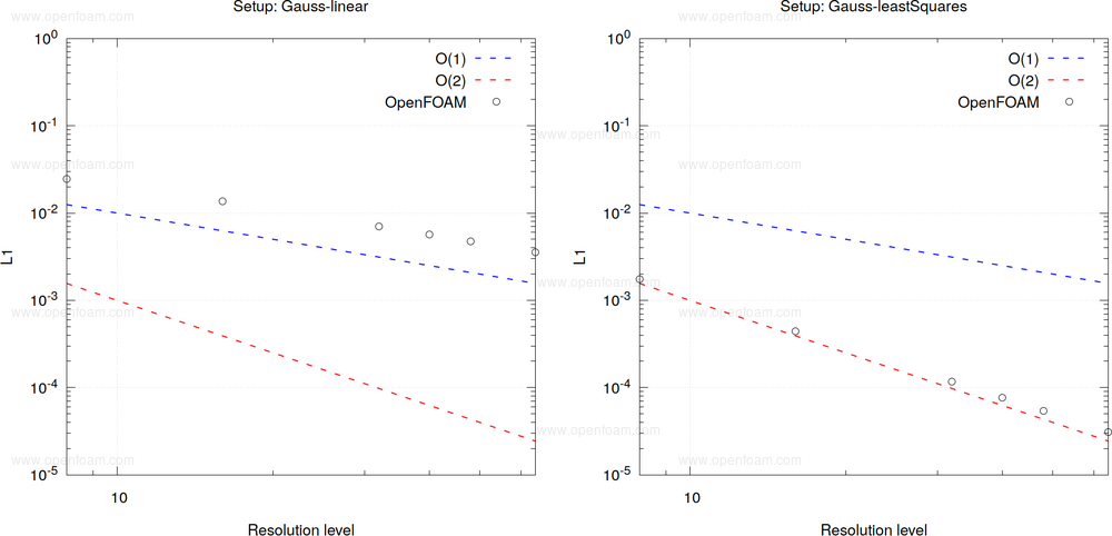
Linear-based edge interpolation schemes for Finite Area can introduce high errors in surface gradient and divergence calculations. The new leastSquares scheme is based on the work of Pesci (2019; p. 29-30, 45-50) - showing similarities to the pointLinear scheme in the Finite Volume framework. Tests showed that the new scheme can improve the surface gradient and divergence results with respect to analytical solutions.
A comparison between Gauss linear and Gauss leastSquares with respect to an analytical solution (Pesci, 2019; Fig. 4.2) shows the improvement in the level of prediction accuracy:
Source code
References
- Pesci, C. (2019). Computational analysis of fluid interfaces influenced by soluble surfactant. Darmstadt, Technische Universität. PhD thesis.
Merge request
TOP
Alternative surface formats
The MappedFile function, which is used when coupling to external data sources, has been extended to support alternative surface reading formats. This allows, for example, sampled EnSight data to be reused for mapping, having the benefit of combining extracted data, visualisation data and input data into a single source.
Field filtering
MappedFile now provides the possibility of adding multi-sweep median filtering of the input data. This can be used to remove higher spatial frequencies when sampling onto a coarse mesh. For example, to apply a linear, area-weighted filter with 5mm search radius:
filterRadius    5e-3;
filterSweeps    40;
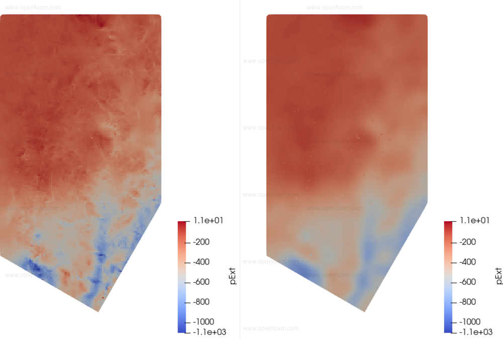
The input field values are then averaged filtered by the specified number of sweeps. This filtering removes higher spatial frequencies that would otherwise taint the sampled values. The effect of the filter is seen in the following:
The left image is the original raw input data, the right is the same after filtering within the MappedFile to remove the high-frequency components.
Source code
Merge request
Tutorial
Preview of field filtering
The new smoothSurfaceData utility provides a simple means of testing the effects of different filter radii and sweeps prior to using in MappedFile.
TOP
The DEShybrid scheme, based on the work of Travin et al. [3], enables solution-dependent blending between a lower-dissipation scheme in vorticity-dominated regions of fine mesh, and a more robust scheme in irrotational or coarse mesh regions. The original scheme was found to malfunction when used with the new grey-area enhanced DES models: The more dissipative scheme was activated in the important early shear layer region, counteracting the model improvements [1].
An update to the DEShybrid scheme is included in the v2212 release, which ensures low-dissipation behaviour in grey-area region and behaves like the original scheme in other respects.
Tutorial
Settings for the new DEShybrid scheme can be found in the new tutorial based on the 2D hump case of Greenblatt et al. [2].
Source code
Attribution
- The updated DEShybrid scheme was implemented by Upstream CFD GmbH and integrated into OpenFOAM in collaboration with OpenCFD Ltd with funding by Volkswagen AG.
- Merge request MR!560
References
- Fuchs, M., Mockett, C., Sesterhenn, J., and Thiele, F. (2015). Assessment of novel DES approach with enhanced SGS modelling for prediction of separated flow over a delta wing. 22nd AIAA Computational Fluid Dynamics Conference, Dallas / Texas, AIAA-2015-3433.
- Greenblatt, D., Paschal, K. B., Yao, C.-S., Harris, J., Schaeffler, N. W., and Washburn, A. E. (2006). Experimental Investigation of Separation Control Part 1: Baseline and Steady Suction. AIAA Journal, Vol. 44, No. 12, pp. 2820-2830, 2006.
- Travin, A.K., Shur, M.L., Strelets, M.K., and Spalart, P.R. (2004). Physical and numerical upgrades in the detached-eddy simulation of complex turbulent flows. Advances in LES of complex flows, pp. 239–254, 2004.