
v2112: New and updated solvers and physics
TOP
The new velocityFilmShell liquid film regionFaModel has been added to the set of solid-thermal and vibro-acoustic Finite Area (FA) models that can be used with any incompressible solver, e.g. pimpleFoam. This model solves the shallow film momentum equations for an adiabatic, incompressible fluid on a surface. Functionality is similar to the existing finite volume-based film modelling, with the significant benefit of being applicable to complex geometry.
The model operates as a velocity boundary condition on the 3D mesh, e.g.:
car
{
    type            velocityFilmShell;

    active          true;
    infoOutput      false;

    deltaWet        1e-5;   // Thickness to consider the face wet
    U               U;      // Name of the primary region velocity
    p               p;      // Name of the primary region pressure

    pRef            1e5;    // Reference pressure for thermo
    T0              300;    // Reference temperature for thermo

    zeroWallVelocity true;  // Zero velocity applied to the primary region

    // Thermo for the film flow
    thermo
    {
        H2O;
    }

    // Turbulence model
    turbulence          laminar;

    laminarCoeffs
    {
        friction        linearProfile;  // Wall friction model
        shearStress     simple;         // Type of wall friction model
        Cf              0.01;           // Gas friction coefficient
    }

    // Mass loss model injected into a lagrangian cloud
    injectionModels
    (
        curvatureSeparation
    );

    curvatureSeparationCoeffs
    {
        minInvR1          10;
        deltaByR1Min      0.04;
    }

    // Extra forces on the film
    forces
    (
        perturbedTemperatureDependentContactAngle
    );

    perturbedTemperatureDependentContactAngleCoeffs
    {
        Ccf     0.085;
        theta   constant 45;
        distribution
        {
            type            normal;
            normalDistribution
            {
                minValue        50;
                maxValue        100;
                expectation     75;
                variance        100;
            }
        }
    }

    // Name of the finite area region
    region              film;

    // Model used for the liquid film
    liquidFilmModel     kinematicThinFilm;

    value               uniform (0 0 0);
}
Where the entries comprise:
- zeroWallVelocity : set the velocity boundary condition to zero, i.e. as a no-slip wall condition. If set to false the wall velocity is given by the film velocity parallel to the patch. Setting this value to true tends to be more stable.
- deltaWet : the minimum film thickness to be considered 'wet'. This is used to locate the edge of the film between dry and wet faces.
- pRef and T0 : reference working pressure and temperature for the film properties. Note that the current implementation assumes that the film is isothermal and incompressible.
- thermo : film fluid thermophysical properties.
- turbulence : film turbulence model; note that only the laminar model is currently available.
- laminarCoeffs : coefficients for laminar models:
- shearStress : gas friction model. There are two options:
- simple : assumes : friction = Cf (Up - Ufilm)
- wallFunction : uses the stress from the primary region turbulent wall function or the laminar stress friction tensor.
- friction : friction between wall and film. Here there are four options depending on the assumed film velocity profile:
- quadraticProfile
- linearProfile
- DarcyWeisbach
- ManningStrickler
- shearStress : gas friction model. There are two options:
- injectionModels : enables mass injection from the film into a Lagrangian cloud. Only the curvatureSeparation model is available, which creates parcels at a minimum curvature ratio (minInvR1) for a minimum film thickness (deltaByR1Min).
- forces : specify extra forces acting on the film. At the moment only a contact angle force model (perturbedTemperatureDependentContactAngle) is available.
- liquidFilmModel : sets the model used to evolve the film. Currently the only selection is kinematicThinFilm which solves the standard shallow film equations.
In the case that a film is used with a kinematic Lagrangian cloud, it is necessary to specify the surfaceFilmModel kinematicSurfaceFilm in the constant/kinematicCloudProperties file.
Source code
Tutorials
TOP
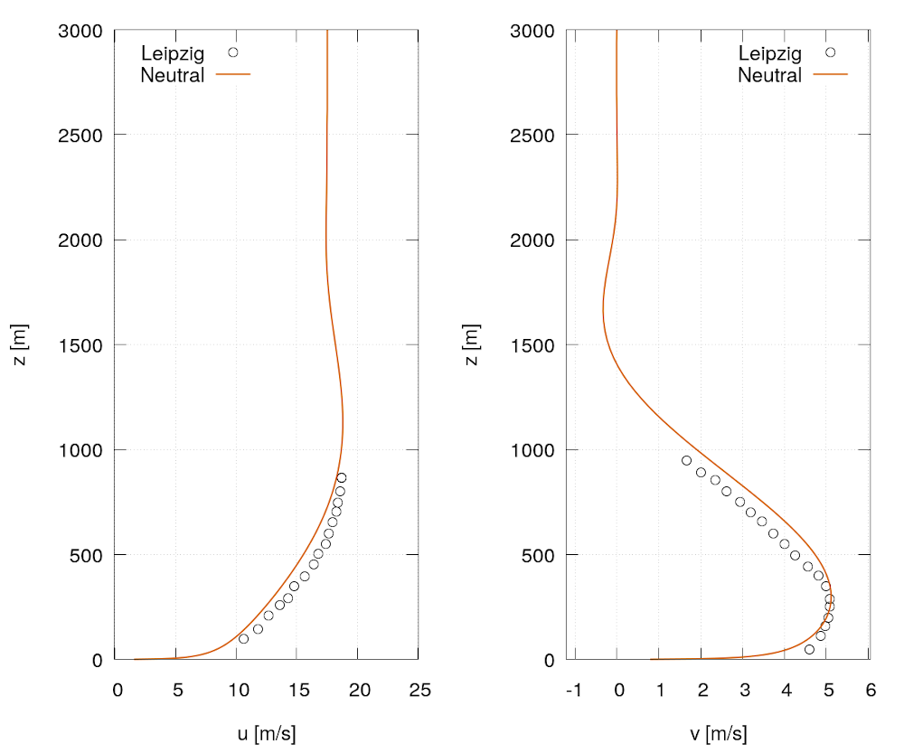
A new one transport-equation linear-eddy-viscosity RANS turbulence closure model, named kL, has been implemented based on the work of Axell & Liungman, 2001 and Wilson & Flesch, 1999 for incompressible and compressible geophysical applications.
Turbulence kinetic energy, k, is computed using a transport equation and the turbulence length scale, L, computed using an expression that depends on the local stratification, and spatiotemporal-variant terrain, e.g. partially forestry plain.
The new model offers a reduction in numerical costs compared to more complex models, e.g. kEpsilon, without the loss of accuracy.
Results from a verification case based on the field experiment of Lettau, 1950 where ground-normal velocity profiles affected by buoyancy forces, Coriolis forces and simple plantation are shown below:
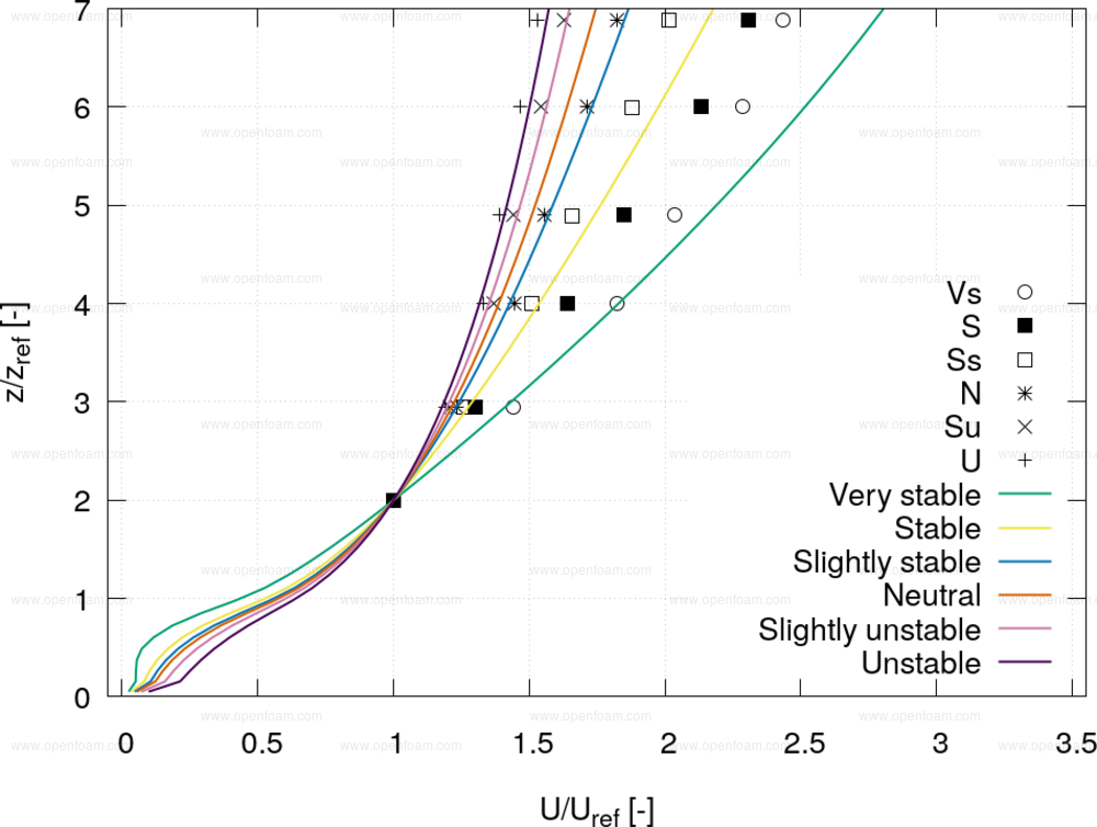
A further verification case based on the more recent field experiment of Arnqvist et al., 2015 where atmospheric stability effects manifest themselves is shown below:
Source code
Tutorial
Merge request
References
- Axell, L. B., & Liungman, O. (2001). A one-equation turbulence model for geophysical applications: comparison with data and the k−ε model, Environmental Fluid Mechanics, 1(1), 71-106.
- Wilson, J. D., & Flesch, T. K. (1999). Wind and remnant tree sway in forest cutblocks. III. A windflow model to diagnose spatial variation. Agricultural and Forest Meteorology, 93(4), 259-282.
Attribution
- OpenCFD would like to thank Hamza Musaddiq (ENERCON Gmbh) for the initial implementations of various functionalities and useful discussions.
TOP
The patchInjection model now has an optional velocityType entry that can be set to:
- fixedValue : (default) same as earlier versions, requires U0 entry
- patchValue : velocity set to seed patch face value
- zeroGradient : velocity set to seed patch face adjacent cell value
The following animation shows an example using the new patchValue option
Example usage:
model1
{
    type            patchInjection;
    massTotal       1;
    SOI             0;
    parcelBasisType mass;
    patch           cylinder;
    duration        10;
    parcelsPerSecond 100;
    velocityType    patchValue; // new entry
    //velocityType    zeroGradient;
    //U0              (-10 0 0);
    flowRateProfile constant 1;
    sizeDistribution
    {
        type        normal;
        normalDistribution
        {
            expectation 1e-3;
            variance 1e-4;
            minValue 1e-5;
            maxValue 2e-3;
        }
    }
}
Source code
Tutorial
TOP
A new mass transfer model, interfaceOxideRate, has been added to the framework of the icoReactingMultiphaseInterFoam solver. This model is designed to predict oxide formation at the interface of two phases, i.e air and liquid, due to the oxidation process triggered by the oxygen in the air interacting with a liquid metal.
The model predicts the mass transfer of the liquid phase into the oxide liquid phase. The transfer is calculated at the phase interface determined by a user value of the phase fraction, e.g. alpha.liquid = 0.7, based on the interface temperature and a critical value above which the reaction stops; note that chemistry is not considered in the model. An example input for the phaseProperties dictionary:
massTransferModel
(
    (liquid to oxide)
    {
        type        interfaceOxideRate;
        C           20;
        Tsolidus    823.15;
        Tliquidus   884.15;
        oxideCrit   1e-3;
        isoAlpha    0.9;
        ...
    }
);
To accommodate oxide absorption at walls, as observed in real-world scenarios, the new timeVaryingMassSorption is employed, specified as:
{
    type        timeVaryingMassSorption;
    kabs        1e1;
    max         1e-3;
}
where:
- kabs is the rate of absorption [1/sec]
- max is the maximum volumetric fraction in the wall
The volume absorbed in the wall is subtracted on the fluid on cells next to the patch.
Source code
Tutorial
Reference
- O Cao, L., Sun, F., Chen, T., Tang, Y., & Liao, D. (2018). Quantitative prediction of oxide inclusion defects inside the casting and on the walls during cast-filling processes. International Journal of Heat and Mass Transfer, 119, 614-623.
TOP
The alphatWallBoilingWallFunction boundary condition is used to model a boiling fluid using a set of different heat transfer correlations depending on the fluid regimen, thermal properties of the fluid and geometrical features of the set up. The first version was introduced in OpenFOAM v1906 with the solver chtMultiRegionTwoPhaseEulerFoam.
In this release the boundary condition has been extended to deal with liquid hydrogen via an extra set of correlations for each regime:
- Film boiling : BreenWestwater - Breen B.P., Westwater J.W. Effect of diameter of horizontal tubes on film boiling heat transfer. Chem. Eng. Progr. 58. No 7. 1965
- Critical Heat Flux (CHF) - T.C. Hua, J.J. Xu, Quenching boiling in subcooled liquid nitrogen for solidification of aqueous materials, Mater. Sci. Eng. A 292 (2000) 169–172.
- Nucleate sub-cooling : Kutadeladze and exponential - Correlations for calculating heat transfer of hydrogen pool boiling. Lei Wang, Yanzhong Li, Feini Zhang, Fushou Xie, Yuan Ma Int journal of hydrogen energy 41 2016 17118 - 17131.
- Sub-cool critical heat flux : Tatsumoto - Shirai-Tatsumoto, Shiotsu, Hata, Kobayashi, Naruo, Inatani, Boiling heat transfer from a horizontal flat plate in a pool of liquid hydrogen. Cryogenics 50 (2010) 410-416.
- Temperature departure from nucleating boiling (TDNB): Shirai - Shirai-Tatsumoto, Shiotsu, Hata, Kobayashi, Naruo, Inatani, Boiling heat transfer from a horizontal flat plate in a pool of liquid hydrogen. Cryogenics 50 (2010) 410-416. Note that the correlation is based on fitting data from Fig 11; suitable for liquid Helium, Nitrogen, Oxygen and Hydrogen
The new option to select a nucleate sub-cool correlation instead of using the standard RTI model is available.
A minimal example illustrating the usage of the boundary condition:
<patchName>
{
    type            compressible::alphatWallBoilingWallFunction;
    otherPhase      gas;
    phaseType       liquid;
    Prt             0.85;
    Cmu             0.09;
    kappa           0.12;
    E               9.8;
    relax           constant 1;
    dmdt            uniform 0;

    partitioningModel
    {
        type        Lavieville;
        alphaCrit   0.2;
    }
    LeidenfrostModel
    {
        type        Spiegler;
        Tcrit       33.32;
    }
    nucleateFluxModel
    {
        type        exponential;
        a           6309;
        b           2.52;
    }
    CHFModel
    {
        type        Zuber;
        Cn          0.16;
    }
    CHFSubCoolModel
    {
        type        Tatsumoto;
        K           0.23;
    }
    MHFModel
    {
        type        Jeschar;
        Kmhf        0.031;
    }
    TDNBModel
    {
        type        Shirai;
        Tc          33.32;
        Pc          1.30e+06;
    }
    filmBoilingModel
    {
        type        BreenWestwater;
        Cn          0.37 ;
    }

    value           uniform 1e-8;
}
Source code
Tutorial
TOP
The isoAdvection class has been extended to handle cells partially filled with a porous medium, i.e. only the remaining part is accessible for fluid flow. For interface advection, the main effect is that for given face fluxes the fluid interface will move faster because a cell fills up faster when it is partially filled by a porous medium. The porosity is specified by the user via a porosity volScalarField, placed in the time directory, where a cell porosity:
- of 1 indicates an empty cell (no porous medium);
- between 0 and 1 indicates how much of the cell's volume is accessible to fluid flow.
The volume fraction field, alpha1, describes the fraction of the accessible cell volume that is occupied by the 'coloured' fluid. Thus, if celli has porosity = 0.5 and alpha1 = 0.5 then 25% of the cell’s total volume is occupied by coloured fluid.
The velocity, U, with which to construct an isoAdvection object should be the continuous filter/superficial velocity and not the (faster and potentially discontinuous) pore/intrinsic velocity with which the interface moves. The pore velocity can be obtained by dividing U by porosity. The face flux, phi, used to construct an isoAdvection object remains the volumetric flux such that for incompressible fluids, the sum of phi over the faces of a cell should be zero regardless of the porosity field.
For the porosity field to be read by an isoAdvection object, a case must have a constant/porosityProperties dictionary with the switch:
porosityEnabled true;
For a simple test case demonstrating the implementation, see: $FOAM_TUTORIALS/multiphase/interIsoFoam/discInConstantPorousFlow
InterIsoFoam with porous media
The interIsoFoam solver has been modified to incorporate porous media in the momentum equation. The required modifications are the inclusion of added mass and porous friction terms as well as accounting for the reduced available space for fluid flow in cells with porosity < 1. Porosity parameters are set in the JensenEtAl2014 sub-dictionary in constant/porosityProperties (see reference below for explanations of the parameters in the sub-dictionary).
Tutorial
- $FOAM_TUTORIALS/multiphase/interIsoFoam/discInConstantPorousFlow
- $FOAM_TUTORIALS/verificationAndValidation/multiphase/interIsoFoam/porousDamBreak
References
- Missios, K., Jacobsen, N. G., Moeller, K., & Roenby, J. Using the isoAdvector Geometric VOF Method for Interfacial Flows Through Porous Media. MARINE 2021
- Jensen, B., Jacobsen, N. G., & Christensen, E. D. (2014). Investigations on the porous media equations and resistance coefficients for coastal structures. Coastal Engineering, 84, 56-72.
Acknowledgements
- Code contributors:
- Konstantinos Missios
- Niels Gjøl Jacobsen
- Henning Scheufler
- Kutalmış Berçin
- Johan Roenby
- With support from the ESI-OpenCFD and the OpenFOAM Marine Technical Committee.
- The implementation was partially sponsored by Deltares.