4.2 Boundaries
In this section we discuss the way in which mesh boundaries are treated in OpenFOAM. We first need to consider that, for the purpose of applying boundary conditions, a boundary is generally broken up into a set of patches. One patch may include one or more enclosed areas of the boundary surface which do not necessarily need to be physically connected.
4.2.1 Specification of patch types in OpenFOAM
The patch types are specified in the mesh and field files of a OpenFOAM case. More precisely:
- the base type is specified under the type keyword for each patch in the boundary file, located in the constant/polyMesh directory;
An example boundary file is shown below for a sonicFoam case
17
186
19(
20 inlet
21 {
22 type patch;
23 nFaces 50;
24 startFace 10325;
25 }
26 outlet
27 {
28 type patch;
29 nFaces 40;
30 startFace 10375;
31 }
32 bottom
33 {
34 type symmetryPlane;
35 inGroups 1(symmetryPlane);
36 nFaces 25;
37 startFace 10415;
38 }
39 top
40 {
41 type symmetryPlane;
42 inGroups 1(symmetryPlane);
43 nFaces 125;
44 startFace 10440;
45 }
46 obstacle
47 {
48 type patch;
49 nFaces 110;
50 startFace 10565;
51 }
52 defaultFaces
53 {
54 type empty;
55 inGroups 1(empty);
56 nFaces 10500;
57 startFace 10675;
58 }
59)
60
61// ************************************************************************* //
The type in the boundary file is patch for all patches except those patches that have some geometrical constraint applied to them, i.e. the symmetryPlane and empty patches.
4.2.2 Base types
The base and geometric types are described below; the keywords used for specifying these types in OpenFOAM are summarised in Table 4.1.
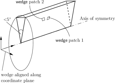
Table 4.1: Basic patch types.
- patch
- The basic patch type for a patch condition that contains no geometric or topological information about the mesh (with the exception of wall), e.g. an inlet or an outlet.
- wall
- There are instances where a patch that coincides with a wall needs to be identifiable as such, particularly where specialist modelling is applied at wall boundaries. A good example is wall turbulence modelling where a wall must be specified with a wall patch type, so that the distance from the wall of the cell centres next to the wall are stored as part of the patch.
- symmetryPlane
- For a symmetry plane.
- empty
- While OpenFOAM always generates geometries in 3 dimensions, it can be instructed to solve in 2 (or 1) dimensions by specifying a special empty condition on each patch whose plane is normal to the 3rd (and 2nd) dimension for which no solution is required.
- wedge
- For 2 dimensional axi-symmetric cases, e.g. a cylinder, the geometry
is specified as a wedge of small angle (e.g.
 ) and 1 cell thick
running along the plane of symmetry, straddling one of the coordinate
planes, as shown in Figure 4.3. The axi-symmetric wedge planes
must be specified as separate patches of wedge type. The details of
generating wedge-shaped geometries using blockMesh are described in
section 4.3.3.
) and 1 cell thick
running along the plane of symmetry, straddling one of the coordinate
planes, as shown in Figure 4.3. The axi-symmetric wedge planes
must be specified as separate patches of wedge type. The details of
generating wedge-shaped geometries using blockMesh are described in
section 4.3.3.
- cyclic
- Enables two patches to be treated as if they are physically connected; used for repeated geometries, e.g. heat exchanger tube bundles. One cyclic patch is linked to another through a neighbourPatch keyword in the boundary file. Each pair of connecting faces must have similar area to within a tolerance given by the matchTolerance keyword in the boundary file. Faces do not need to be of the same orientation.
- processor
- If a code is being run in parallel, on a number of processors, then the mesh must be divided up so that each processor computes on roughly the same number of cells. The boundaries between the different parts of the mesh are called processor boundaries.